WT Week 2
Radio Frequency I
tldr - Antenna & Modulation Techniques
Modulation
The process of altering a carrier wave in order to use it to convey information
Analog Modulation
Amplitude Modulation (AM)
The process of varying the amplitude of the carrier signal accordingly with the amplitude of message signal
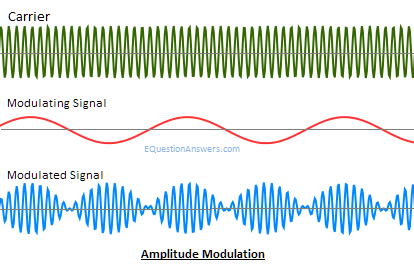 Amplitude Modulation
Frequency Modulation (FM)
The process of varying the frequency of the carrier signal accordingly with the amplitude of the message signal
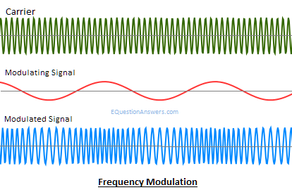 Frequency Modulation
Phase Modulation (PM)
The process of varying the phase of the carrier signal accordingly with the amplitude of the message signal
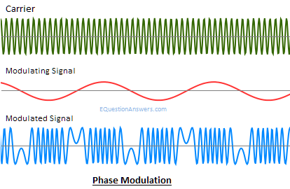 Phase Modulation
Digital Modulation
Amplitude-Shift Keying (ASK)
The process of varying the amplitude of the carrier signal in proportion to the message signal
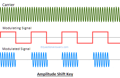 Amplitude-Shift Keying
- Basic form of ASK is On-Off Keying (OOK), where absence of carrier is 0 and presence of carrier is 1
- Used in wireless LAN and Bluetooth
- Multiple amplitude levels can be used to encode groups of bits
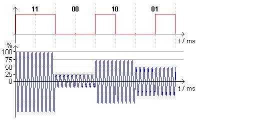 4-level ASK
Frequency-Shift Keying (FSK)
The process of varying the frequency of the carrier signal accordingly with the message signal
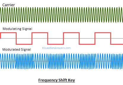 Frequency-Shift Keying
- Output signal varies between 2 predetermined frequencies, logic 1 and logic 0
Phase-Shift Keying (PSK)
The process of shifting the phase of the carrier signal accordingly with the message signal
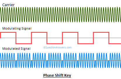 Phase-Shift Keying
- Normally < 8 phases so that phase signals are more distinct
- Constellation diagrams are used to represent the PSK scheme used
Examples
Binary PSK (BPSK)
- Simplest form of PSK
- 2-phase PSK
 BPSK Signals
Quadrature PSK (QPSK)
- Each phase represents a 2-bit group: 00, 01, 10, 11
- 4-phase PSK
 QPSK Signals
Constellation Diagrams
 Constellation Diagrams
The image shows the constellation diagrams for a 4-PSK scheme and an 8-PSK scheme respectively.
Quadrature Amplitude Modulation (QAM)
- The combination of 2-level ASK and QPSK
- QPSK provides the 4 points in the constellation diagram for each amplitude (lines)
- 2-level ASK provides the 2 amplitudes in the constellation diagram (circles)
- Each point represents 3 bits (e.g. 001)
- 1st 2 bits represent the phase (00)
- 3rd bit represents the amplitude (1)
 QAM Constellation Diagram
Radio Frequency (RF) Components
Transmitter
- Generates alternating current (AC) signal upon receiving digital data
- AC signal oscillates 2.4 billion times per second for 2.4 GHz transmissions
- Modifies AC signal by using a modulation technique to encode data into signal
- Transmits modulated AC signal to antenna
Antenna
- A passive conductor
- Relies on power source (transmitter / receiver)
- Collects AC signal received from transmitter and converts electricity into RF waves
- RF waves are radiated away at the transmission end
- Another antenna receives the RF waves
- Converts RF waves into AC electric signals and passes it to the receiver
Receiver
- Receives AC signal from antenna
- Demodulates AC signal into digital data
Properties of Antenna
Signal Strength
Loss
Signal energy decreased
- RF signal received is weaker
- Signal strength affected by
- Distance
- Noise
- Absorption
- Reflection
- Refraction
- Diffraction
- Scattering
Gain
Signal energy increased
- Signal energy focused in one direction
- Signal is put through an amplifier
Absorption
- Signal is absorbed if it does not bounce off, move around or pass through an object
- 2.4 GHz signal passed through a brick & concrete wall will be 1/16 the original power (Fun fact)
Reflection
- Signals may bounce in an unintended direction when it hits a smooth object
- Causes serious performance issues in WIFI
- Multiple reflected signals degrade the signal’s strength and quality
Diffraction
- The bending and spreading of signals around an obstruction
- Creates RF shadows, the spot behind the obstruction
- RF shadow may become a dead zone of coverage
- Thus, selecting antenna locations is important!
Refraction
- Signals passing through mediums with different densities can cause the direction of the wave to change
- Commonly occurs as a result of atmospheric conditions
Size of an antenna
Length should be a multiple of the wavelength, such as 1/2 or 1/4
 Length of antenna
Where
- λ is the wavelength (m)
- x is a multiple (etc. 1/2 and 1/4)
Example
Find a suitable length of an antenna for a signal frequency of 100MHz. Assume that the speed of light 3 x 10^8 m/s.
 Solution
Power Ratio
Decibel
Relative measurement used in calculations of gain and loss, to indicate the strength of a signal
- Usually expressed as the logarithmic ratio of the strength of a transmitted signal to the strength of the original signal
Forumla
 P is measured in Watts (W)
Antenna Types
Omni-Directional Antenna
- RF signal spreads out equally in all directions
- Radiated signals form a doughnut shape around the antenna
HIGH-GAIN Omni-Directional Antenna
- Radiates signals in a “flatter” doughnut shape
- Power per unit area increases
- 2 dB gain relative to Omni-Directional design
Directional Antenna
- Reflecting element placed to the left of the antenna’s radiating element
- Signal get directed in a certain direction
- Power per unit area increases more
- 3 dB gain
HIGH-GAIN Directional Antenna
- Signal is radiated to one direction and has a “flatter” shape
- Power per unit area increases even more
- 20 dB gain
fin
Back to top


